Data Release DR4 | 5 Feb 2024
DOI: 10.25914/5M47-S621
Browse table metadata | Documentation | Known issues with this release
💾 Download the full DR4 catalogue
Accessibility: World-wide accessible
Release documentation
DR4 Documentation
Please read and cite the DR4 paper.
- Introduction
- What type of data is provided?
- Sky Coverage and Data Quality
- Data Access
- Caveats and Known Issues
- SkyMapper Detectors
- SkyMapper Filters
- World Coordinate System
- Astrometric Quality
- Photometric Quality
Introduction^ Back to top
This Fourth Data Release further enhances SkyMapper's deep coverage of the Southern sky and improves the photometric homogeneity for the u and v filters. DR4 more than doubles the image dataset compared to DR3. The data processing includes several enhancements over previous DRs. Included in DR4 are images taken between March 2014 and September 2021, with a number of quality cuts applied. Measurements are included from over 15 billion detections covering more than half the sky (field centres up to Declinations of +28°). They correspond to over 700 million unique astrophysical objects from magnitude 9 to 22. (All magnitudes reported on this site are AB mags.) The object identifiers from DR2/DR3 have been retained where appropriate, to facilitate quick checks for revised photometry.
Please address all feedback, suggestions, and bug reports in the first instance to skymapper@anu.edu.au.
What type of data is provided?^ Back to top
DR4 contains reduced images with overscan, bias, flatfield correction and a World Coordinate System (TPV projection) applied, as well as photometric catalogues (both raw detections and object-merged) for objects in each image. Full access to the DR4 database tables is provided through this website and the Virtual Observatory Table Access Protocol (TAP).
Five SkyMapper-specific database tables have been exposed in this data release:
-
dr4.master — mean object astrometry, photometry and shape information from all good detections. This table should be used for most photometric queries and is also exposed through the Cone Search service
-
dr4.photometry — per image object detections and corresponding photometric and shape information. This table is also available to the Cone Search service
-
dr4.images — a listing of image coordinates and exposure information
-
dr4.ccds — a listing of CCD details used by the Image Cutout service
-
dr4.mosaic — a listing of the CCD positions within the SkyMapper mosaic
The dr4.master table has been pre-matched to several other large catalogues:
-
ext.allwise — the NASA Widefield Infrared Survey Explorer (WISE) AllWISE data release
-
ext.catwise2020 (NEW!) — the NASA Widefield Infrared Survey Explorer (WISE) CatWISE2020 data release
-
ext.des_dr2 (NEW!) — the Dark Energy Survey (DES) DR2
-
ext.refcat2 — The ATLAS All-Sky Stellar Reference Catalog (Tonry et al. 2018)
-
ext.gaia_dr3 — the Gaia Mission Catalogue DR3
-
ext.galex_guvcat_ais — the All-sky Imaging Survey from the GALEX catalogs of unique UV sources (GUVcat; Bianchi et al. 2017)
-
ext.ls_dr9 (NEW!) — the DESI Legacy Imaging Surveys (LS) DR9, Sweep Catalogs
-
ext.nsc_dr2 (NEW!) — the NOIRLab Source Catalog (NSC) DR2
-
ext.ps1_dr1 — the Pan-STARRS1 (PS1) DR1 Catalog, selected columns, restricted to decMean<30deg and nDetections>1
-
ext.splus_dr3 (NEW!) — the Southern Photometric Local Universe Survey (S-PLUS) Catalog DR3
-
ext.twomass_psc — the Two Micron All Sky Survey (2MASS) Point Source Catalog (PSC)
-
ext.vhs_dr6 — the VISTA Hemisphere Survey (VHS) DR6
Matching to the external tables was attempted with a 15" search radius around each SkyMapper source and the ID and distance of the nearest source from the those catalogues are noted in sets of columns in dr4.master. As in DR2 and DR3, only the 2MASS PSC was queried (instead of both the PSC and XSC), while for Gaia DR3, the two nearest matches from the catalogue are listed. The distance to the 2nd-nearest match may indicate the presence of a close neighbour affecting the photometry of the primary source (also see the self_id1, self_id2, and self_id3 columns in dr4.master for the three closest DR4 sources to each DR4 object). The ext schema also contains additional photometric catalogues that have not been cross-matched with DR4 (see table metadata here).
We also provide local copies of several spectroscopic and other catalogues, which we have pre-matched to the SkyMapper master table with a 15" search radius, noting the nearest SkyMapper source in the dr4_id and dr4_dist columns of those tables:
-
ext.spec_2dfgrs — the 2 Degree Field Galaxy Redshift Survey (2dFGRS)
-
ext.spec_2dflens — the 2dF Gravitational Lens Survey (2dFLenS)
-
ext.spec_2qz6qz — the 2dF and 6dF QSO Redshift Surveys (2QZ/6QZ)
-
ext.spec_6dfgs — the 6 Degree Field Galaxy Survey (6dFGS)
-
ext.spec_galah_dr3 (NEW!)— the GALAH+ DR3 catalogue
-
ext.spec_gama_dr3 — the Galaxy Mass and Assembly (GAMA) Survey DR3
-
ext.spec_hesqso — the Hamburg/ESO survey for bright QSOs
-
ext.spec_ozdes_dr2 (NEW!) — the Australian Dark Energy Survey (OzDES) DR2
-
ext.spec_rave_dr6 (NEW!) — the Radial Velocity Experiment (RAVE) DR6
-
ext.spec_twomrs — the 2MASS Redshift Survey (2MRS)
-
ext.kids_dr4p1 (NEW!) — the Kilo-Degree Survey (KiDS), v4.1
-
ext.milliquas_v8 (NEW!) — the Million Quasar catalog, v8
-
ext.vsx_20230626 (NEW!) — the AAVSO International Variable Star Index, v2023-06-26
To aid in constructing your ADQL queries, you can browse the column metadata of all these tables here.
Sky Coverage and Data Quality^ Back to top
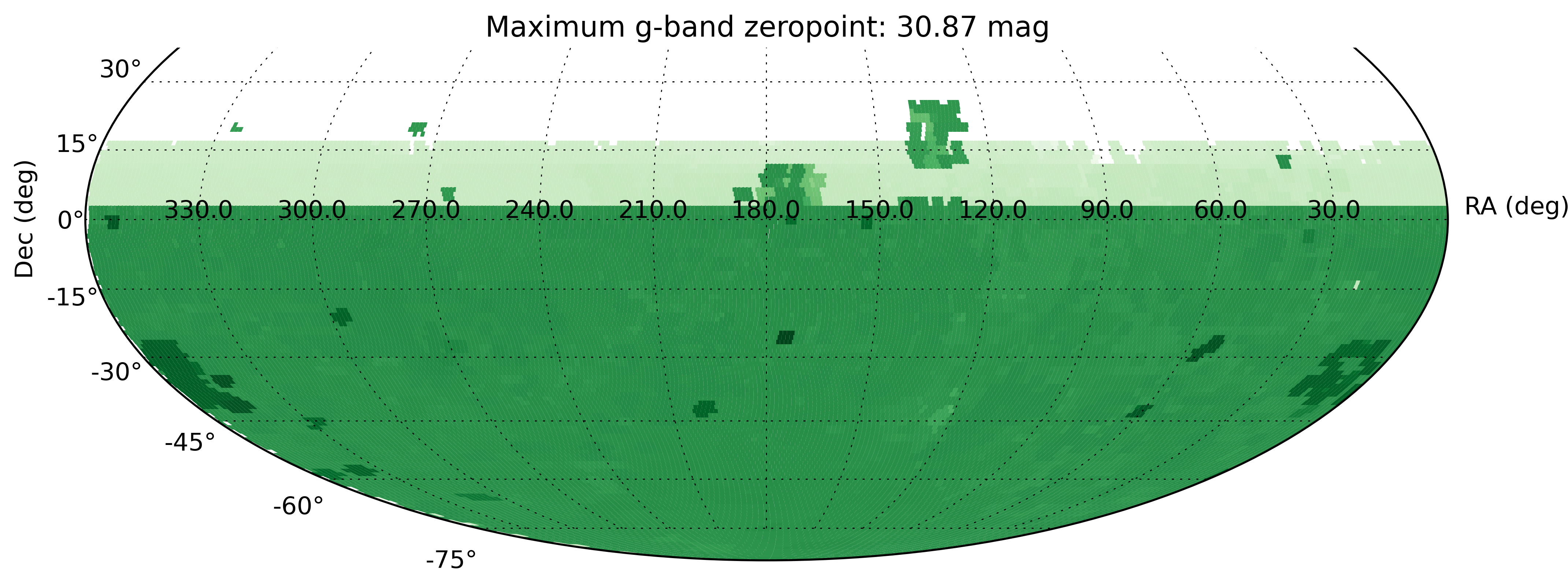
DR4 covers a total area of over 26,000 deg2 (see coverage maps per filter below).
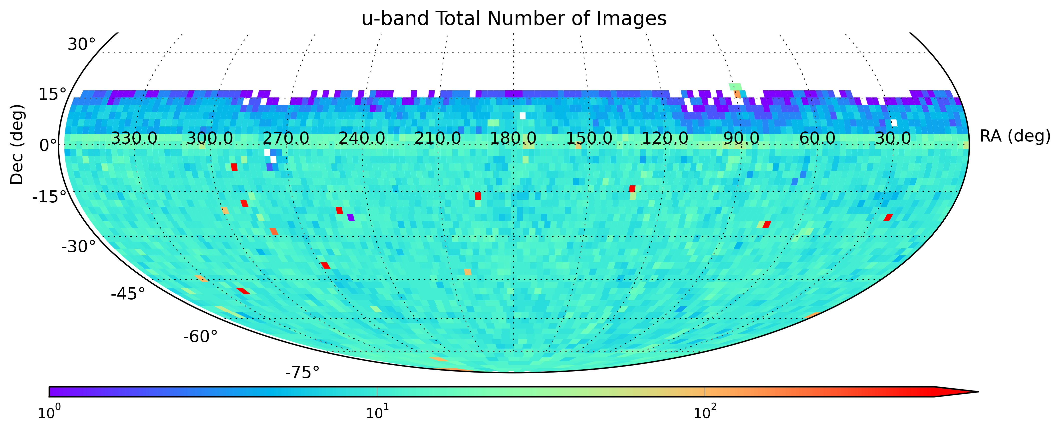
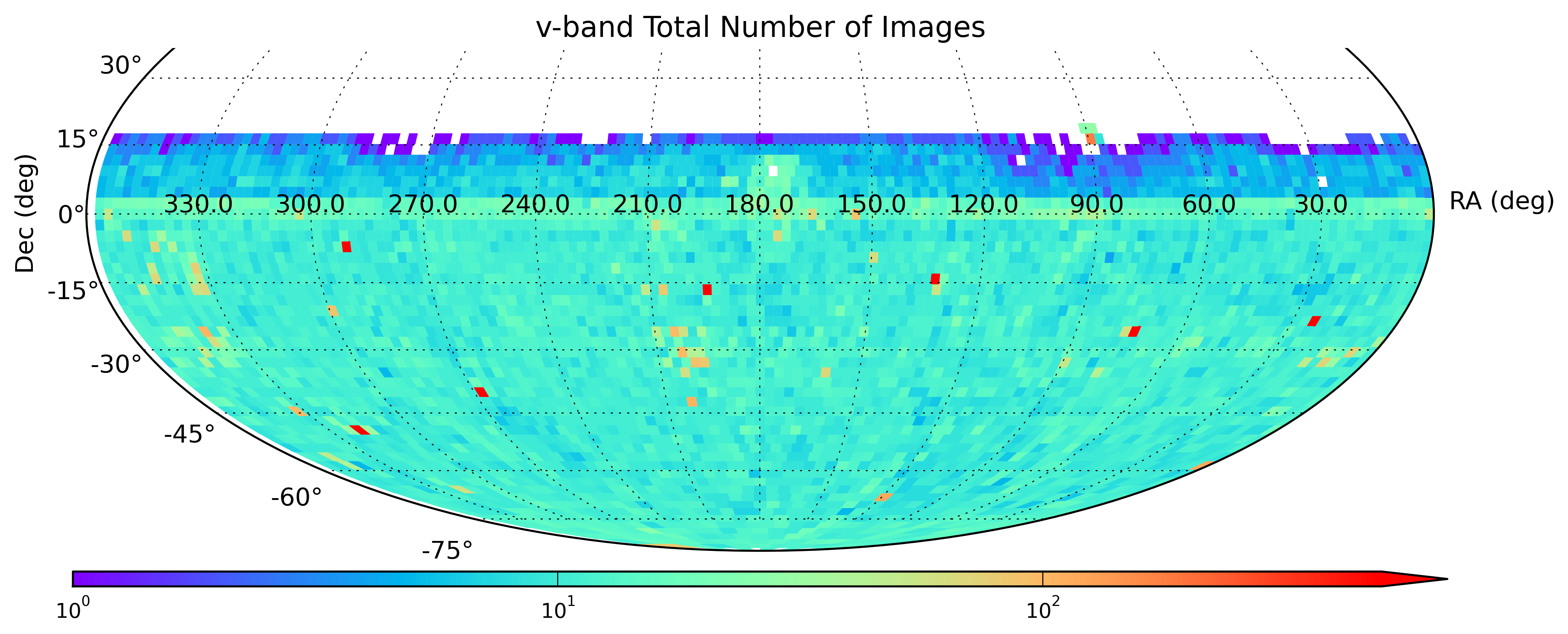
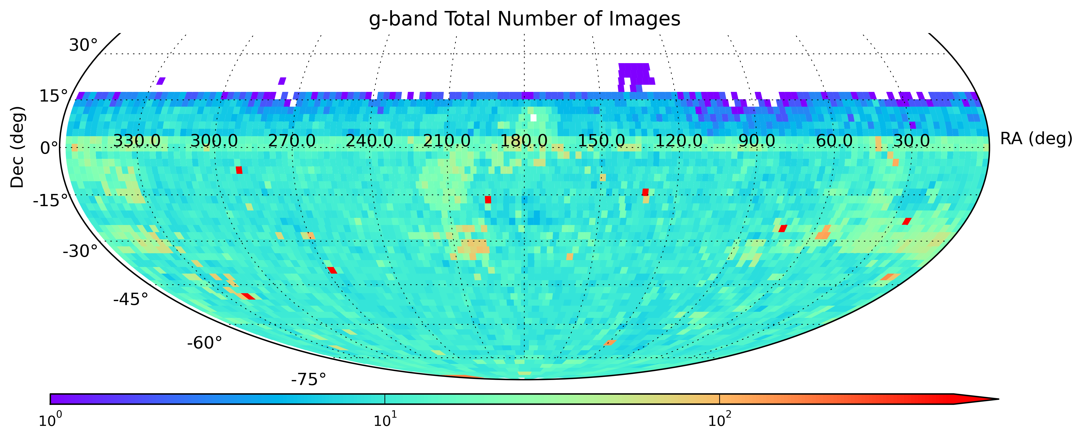
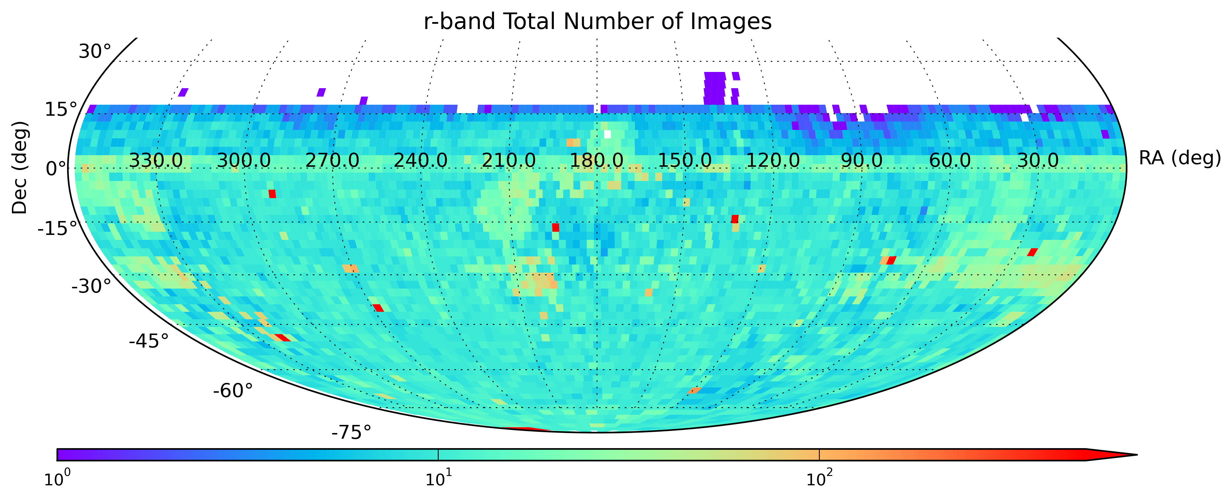
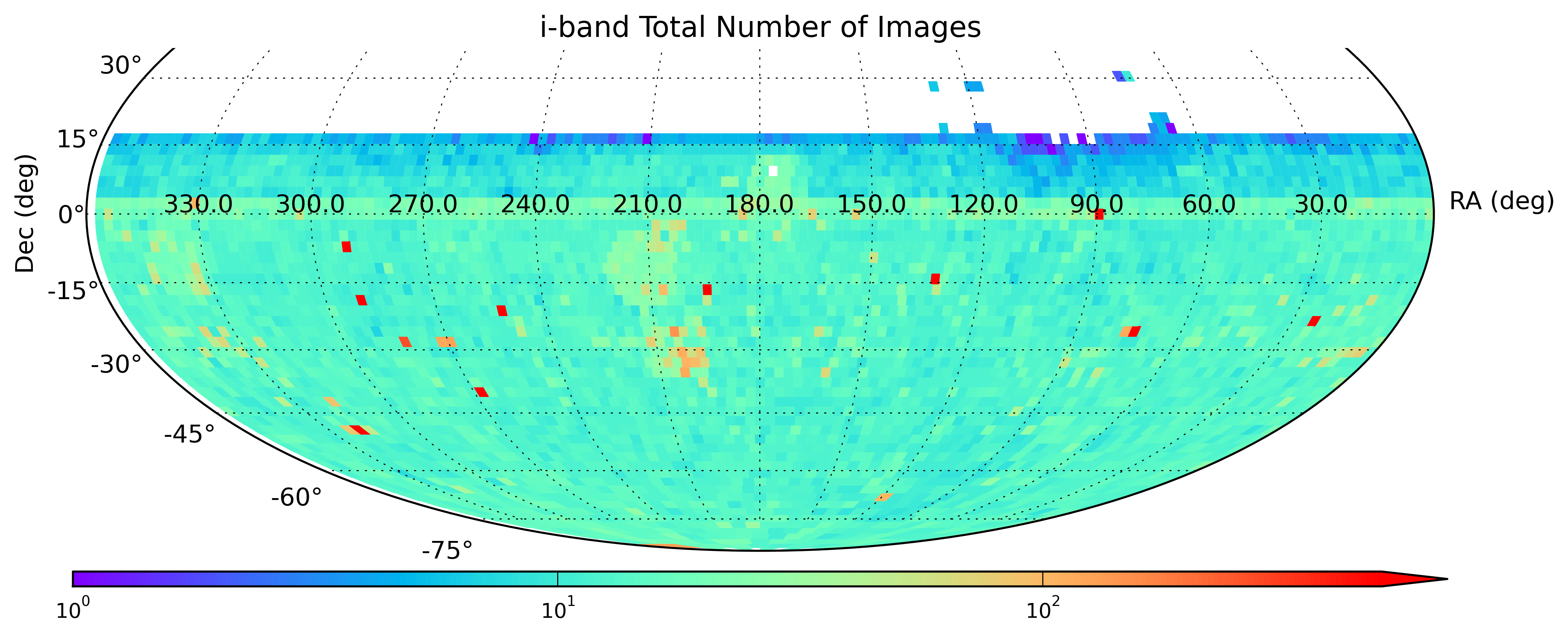
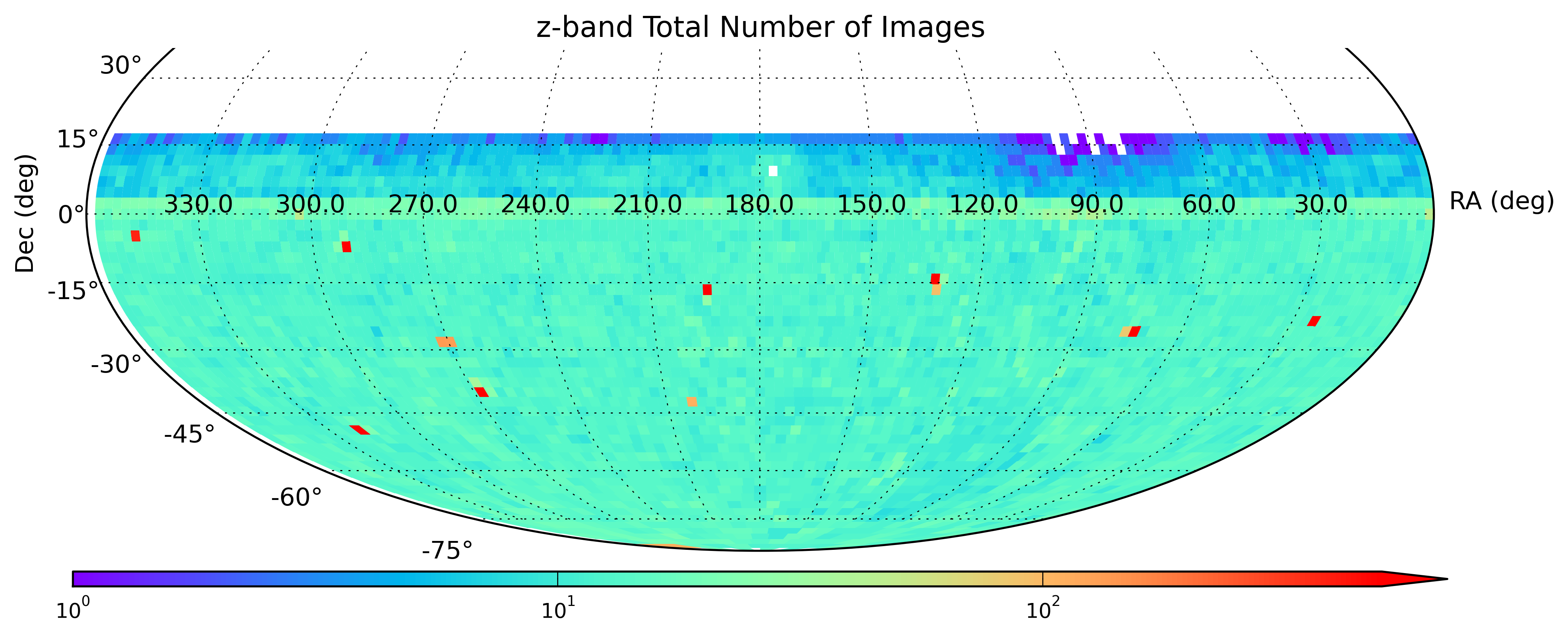
The 417,223 images in DR4 are comprised of 47% Shallow Survey (SS) and 29% Main Survey (MS) frames, and, for the first time, incorporates repeat visits to eight CALSPEC standard star fields (11%) as well as images from the SkyMapper Transient Survey (SMT; 8%; Scalzo et al. 2017) and non-survey images collected for smaller science programs (5%).
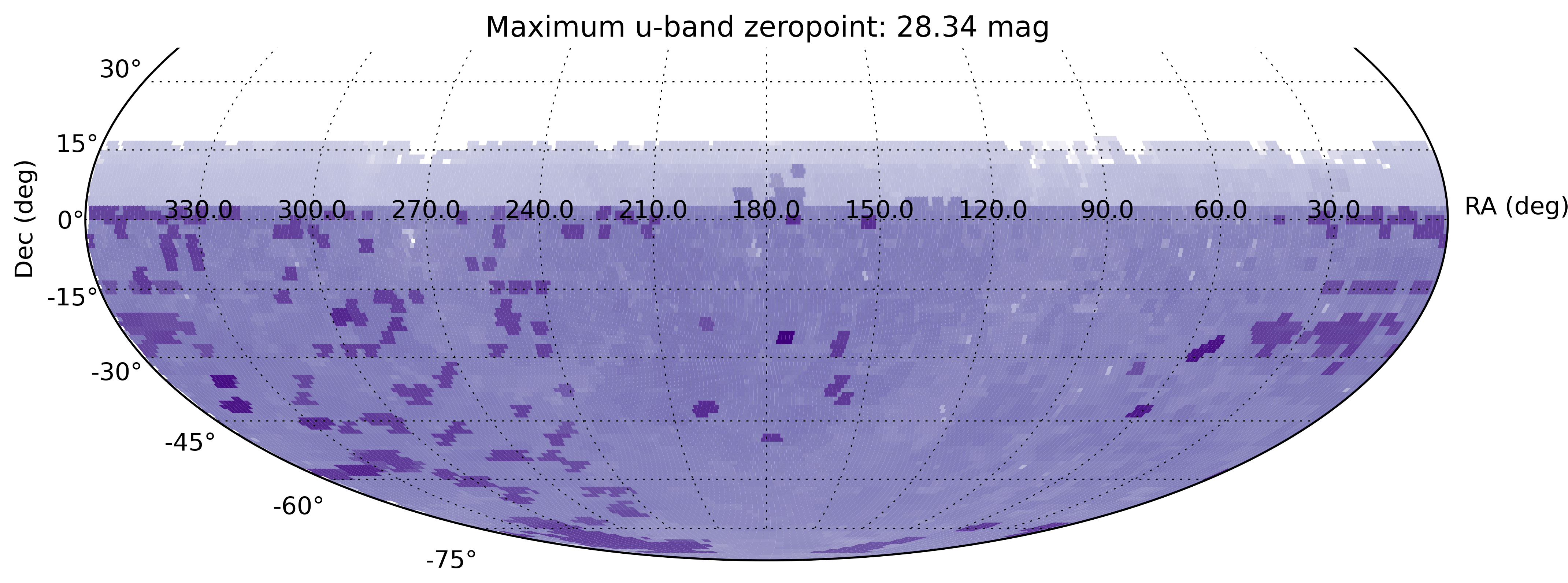
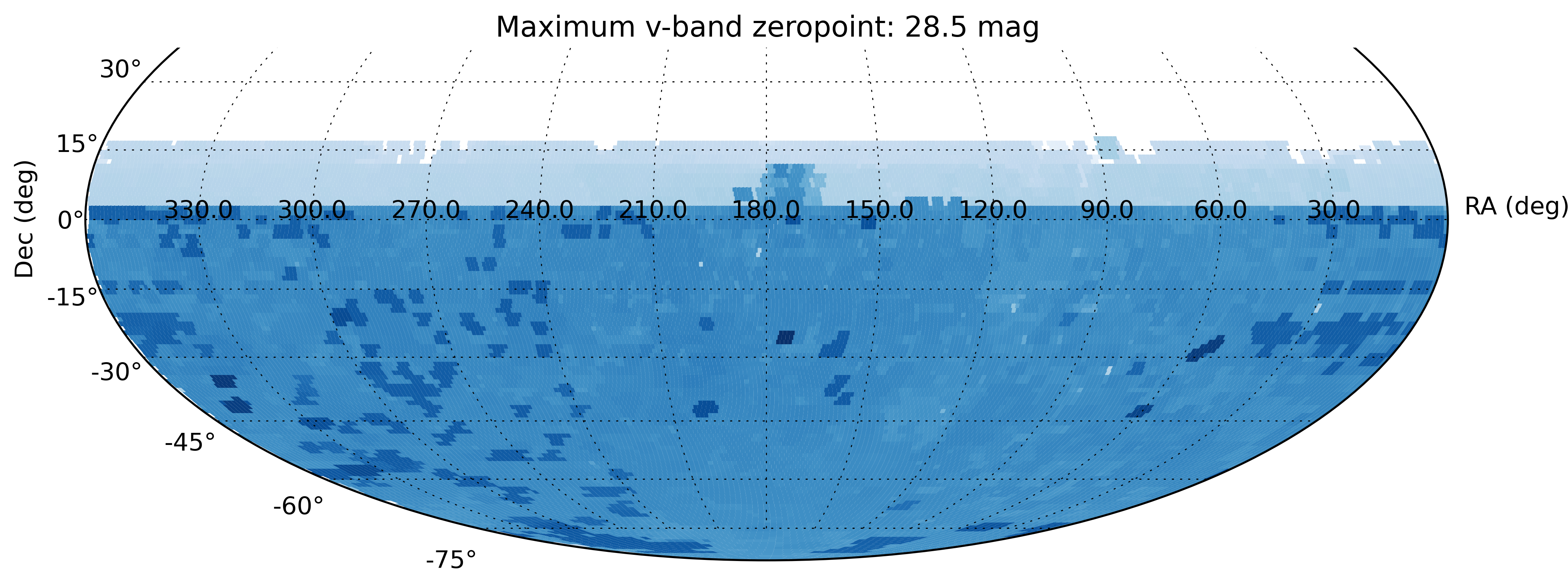
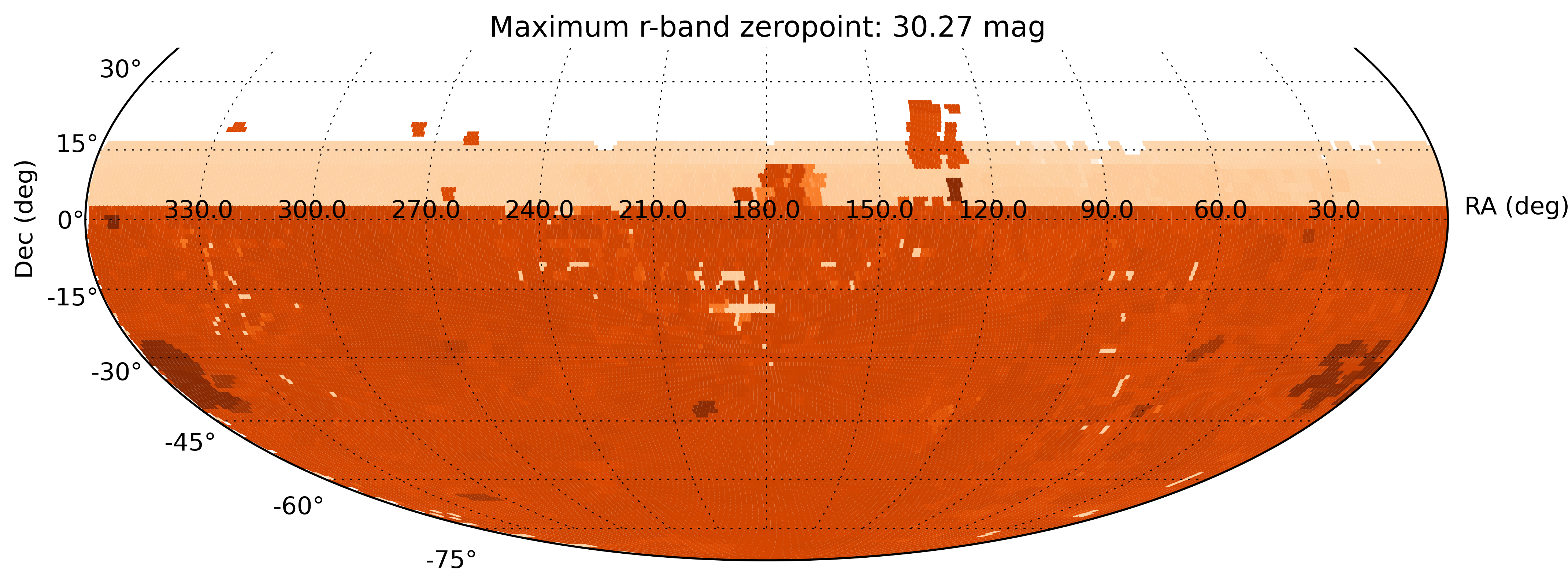
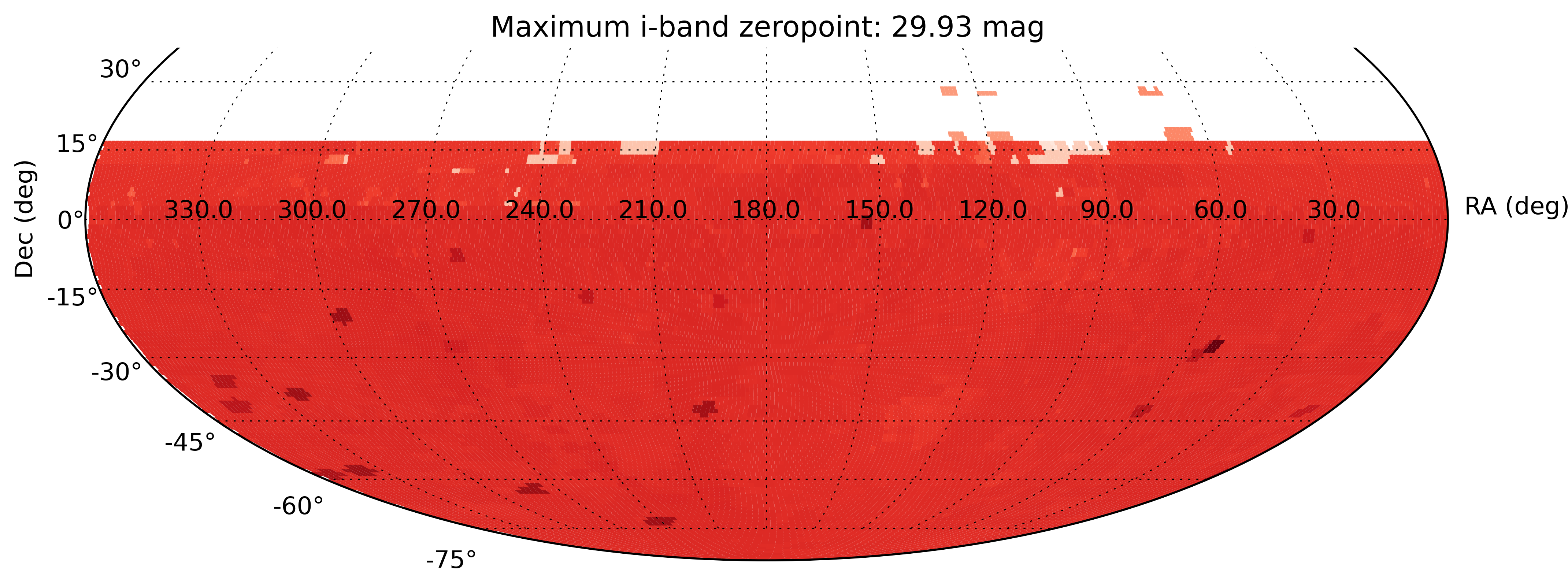
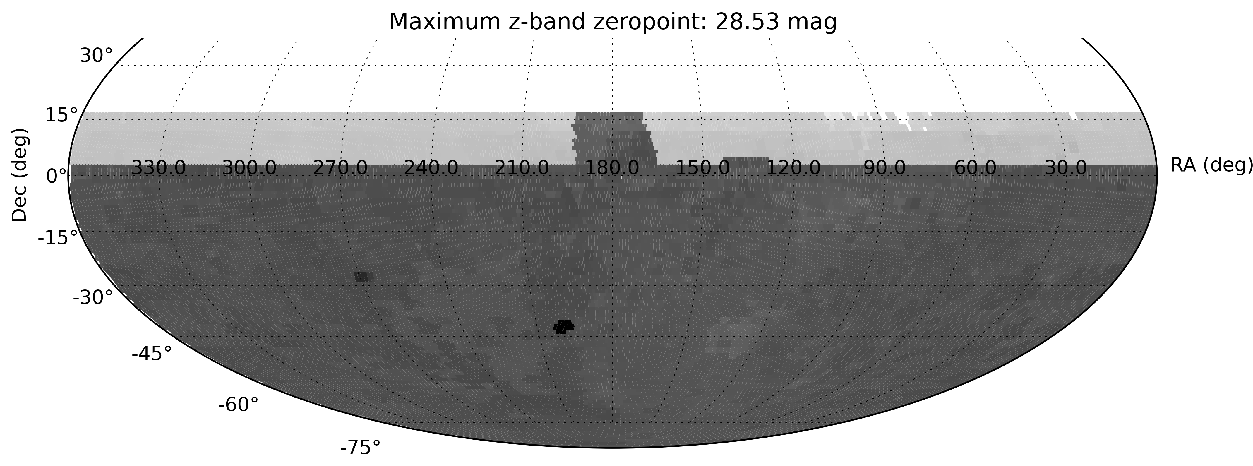
The maximum photometric zeropoint (the magnitude equivalent to one detected count in the image) is shown in each of the 6 sky maps below (in which darker colours are deeper images). The typical 5-sigma detection limits are 7-7.5 magnitudes brighter than the indicated zeropoint.
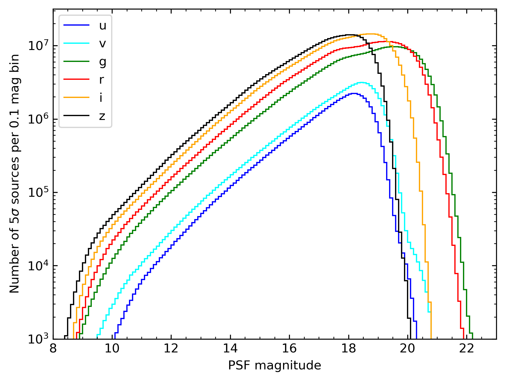
To indicate the imaging depth, the logarithmic number counts of sources with < 5% errors are shown in the figure below, with the bimodal distributions principally reflecting the Shallow Survey and Main Survey components.
Median seeing in DR4 is (3.3", 3.1", 2.9", 2.6", 2.6", 2.5") for (u, v, g, r, i, z), and is typically slightly better in Main Survey images than in the Shallow Survey. We have included images with a PSF FWHM of up to 5" and an elongation of up to 1.4.
All source detections in the photometry table include the Source Extractor flags, complemented by additional flags from our data processing in a higher bit range:
From Source Extractor:
| Flag Bit | Meaning |
|---|---|
| 1 | The object has neighbors, bright and close enough to significantly bias the photometry, or bad pixels (more than 10% of the integrated area affected). |
| 2 | The object was originally blended with another one. |
| 4 | At least one pixel of the object is saturated (or very close to). |
| 8 | The object is truncated (too close to an image boundary). |
| 16 | Object's aperture data are incomplete or corrupted. |
| 32 | Object's isophotal data are incomplete or corrupted. |
| 64 | A memory overflow occurred during deblending. |
| 128 | A memory overflow occurred during extraction. |
Our post-processing adds the following flags, as needed:
- Bit value 256: set for potentially over-split objects, where an image contains multiple detections associated to the same object_id.
- Bit value 512: set for very faint detections that we consider dubious and a potential source of error. Our approach makes sure that very faint detections in the Shallow Survey or Standard Field observations are ignored for the benefit of letting the Main Survey or other deep observations define their distilled properties, while faint detections in deep images are still included into the master table.
- Bit value 1024: set for source detections that appear much more concentrated than PSFs and with small minor axis extent, as they may be affected by uncorrected cosmic rays or transient hot pixels.
- Bit value 2048: set for source detections that are close to bright stars in the ATLAS Refcat2 catalogue, based on a search radius, in degrees, of
log10 (radius) < -0.2 * m,
where m is the PS1-to-SkyMapper transformed magnitude in the band in question, down to limits of (4, 5, 8.5, 8.5, 6, 5) for (u, v, g, r, i, z). These are usually affected by scattered light from the bright star, and have either compromised photometry or are spurious sources. - Bit value 4096: objects have no single detection without aperture-correction issues.
- Bit value 8192: set for sources in the mosaic corners, where the WCS solution tends to become poorly constrained and offsets compared to Gaia DR3 positions typically exceed 1 pixel (0.5"). This region constitutes approximately 0.59% of the field of view (0.65% of pixels, after excluding CCD gaps).
- Bit value 16384: objects that were never detected on any image other than Standard field images; these objects are typically extended and of low surface brightness so that their centroid positions are not well constrained in some of the shallowest Standard field images and thus show up as separate objects not matched properly to the correct astrophysical object.
Only detections with flags<4 and nimaflags<5 are used for distilling photometry into the master table, and hence the averaged magnitudes exclude all measurements with bad flags (flags>=4 or nimaflags>=5). When all detections of an object have bad flags in a passband, then the magnitude errors are nulled to indicate that the magnitudes need to be taken with a grain of salt.
However, all detections with bad flags or those close to bright stars can still be found in the photometry table.
Data Access^ Back to top
Main Page: How To Access
DR4 images and catalogues can be accessed via the tools on this website (see How To Access), which are being developed as part of the Australian All-Sky Virtual Observatory. The TAP (Table Access Protocol), SIAP (Simple Image Access Protocol), and Cone Search services can also be accessed through Virtual Observatory-aware software tools like TOPCAT and Aladin.
For TAP queries, some definitions and constraints worth considering when making selections from the dr4.master catalogue include:
- flags = 0 - no Source Extractor warnings about saturation, close neighbours, edge-of-CCD effects, etc., in any image, ever
- nimaflags = 0 - isophotal aperture clean of bad pixels, saturation, cross-talk, cosmic rays for all detections in the dataset for that source
- ngood > 1 - source well-measured in multiple images (either in the same filter or different filters)
- x_flags = 0, x_nimaflags = 0, x_ngood > 1 - if only concerned with filter x
- For selecting a very clean sample, one might require that every measurement in every filter was free of Source Extractor warnings or bad pixels:
- flags=0 and nimaflags=0
- For selecting a more complete sample, one might only require that there was at least one good (flags<4 and nimaflags<5) photometric data point in the filter in question:
- F_ngood>0 for F in (u,v,g,r,i,z)
- To avoid biased photometry due to neighbours, one can check the distances to the nearest 2 Gaia D3 sources (gaia_dr3_dist1 and _dist2, which show values up to 15arcsec), the distances to the next 3 closest SkyMapper DR4 sources (self_id1, _id2, and _id3), which saturate at 15arcsec), or the flags_psf column (with the bits being set to indicate whether a neighbour is expected to bias the photometry by >1% in each band; bits: 1=z, 2=i, 4=r, 8=g, 16=v, 32=u)
Caveats and Known Issues^ Back to top
For an up-to-date list of known issues and their prospects for resolution, please see the Known Issues section at the bottom of this page. There are several important issues with DR4 data to be aware of:
-
A very small number of objects do not have their detections correctly merged into a single astrophysical object and thus appear twice in the master table, with non-identical positions; often one of the master objects has almost all the detections, and the other has very few.
-
No illumination correction has been applied.
-
Fringe correction is applied to i- and z-band images, but some r-band images show weak fringing effects.
-
The u-band has a ~1% red leak at 700-750 nm wavelength. The relative throughput of the leak is airmass-dependent and can seemingly increase the u-flux of red objects towards higher airmass.
-
Photometry is affected by a spatially-varying PSF across the field-of-view, and the PSF shows trefoil in the corners and generally significant wings.
-
PSF magnitudes are derived from a series of nested annuli that are calibrated per image and per CCD by bright stars and is fit as a function of the image x,y coordinates. Sources with neighbours of equal brightness will have their PSF magnitudes biased by >1% if those neighbours are separated by <5 arcsec. Brighter neighbours have effects even at larger separation, up to 15" distance. The column FLAGS_PSF and the DR4 paper give more details.
-
Extended-source photometry has not been optimised in DR4. As of DR4, we are providing PSF loss-corrected 5” aperture magnitudes ({f}_APC05) and their errors (e_{f}_APC05); colours formed between these are much less noisy than colours formed from two Petrosian magnitudes.
-
The photometric zeropoints have been newly derived by anchoring to bright stars having Gaia DR3 low-resolution spectroscopy. This provides a significantly more homogeneous photometric calibration across the sky, especially for u and v.
SkyMapper Detectors^ Back to top
The SkyMapper mosaic camera contains 32 CCDs of 4096 x 2048 pixels with a plate scale of ~0.50 arcsec/pixel. There are small gaps between the individual CCDs and the resulting field-of view is 2.37 deg x 2.39 deg. The mosaic fill factor is 91% of a 5.68 deg2 field-of-view. Each SkyMapper image is split into its 32 constituent CCDs, which are presented as separate files to the image cutout service.

SkyMapper Filters^ Back to top
The SkyMapper filter curves (with atmosphere) are shown below. We have tabulated colour transformations between SkyMapper and other standard filters, as well as predicted star colours and reddening corrections -- they can be found on the page here.
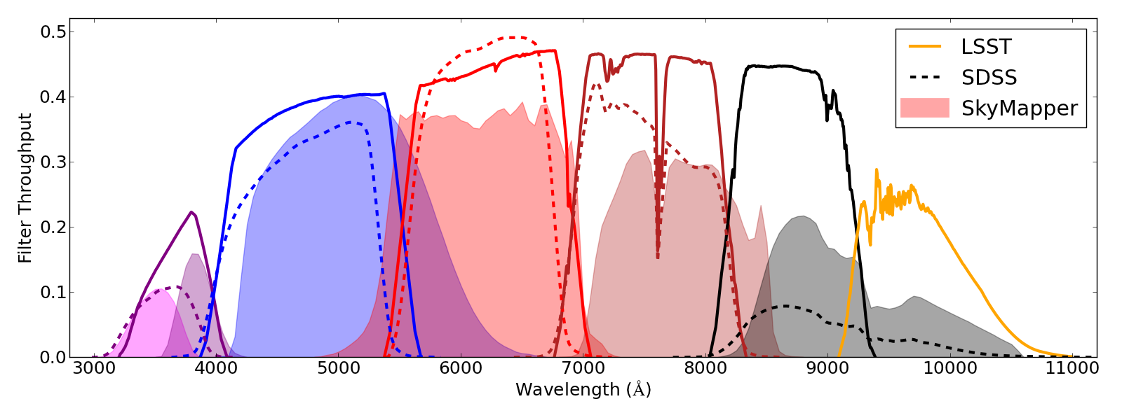
Note that the u-band filter (ultraviolet) is shortward of the Hydrogen Balmer break, while the v-band (violet) is placed between the Balmer break and the Ca H&K 4000AA-break. The u-filter also has a red leak, which needs an airmass-dependent correction. The two lines shown in the figure below are effective transmission curves including atmosphere for airmasses 1 and 2. The third (inset) panel shows the difference between the apparent u-magnitudes observed at airmass 1 and airmass 2 as a function of star colour. The redder the star the brighter it appears in u-band as it is observed closer to the horizon, because calibration stars get fainter, while the red leak keeps the flux bright. Additional information on the filter set can be found in Bessell et al. (2011).

World Coordinate System^ Back to top
Reduced SkyMapper images provided through this website and the SIAP service have been registered onto the sky using the TPV World Coordinate System (RA---TPV, DEC--TPV). TPV builds on the standard TAN projection by adding a general polynomial distortion suitable for wide-field cameras which is described in a set of additional PVi_m keywords. A typical TPV header is reproduced below:
| Typical TPV FITS header |
|---|
WCSAXES = 2 / WCS dimensionality CTYPE1 = 'RA---TPV' / WCS projection type for this axis CTYPE2 = 'DEC--TPV' / WCS projection type for this axis LONPOLE = 180.0 / WCS coordinate rotation: longitude LATPOLE = 0.0 / WCS coordinate rotation: latitude CRVAL1 = 276.914401980 / RA of reference point CRVAL2 = -9.384011927 / DEC of reference point CRPIX1 = -2.900864031 / X reference pixel CRPIX2 = -63.233494932 / Y reference pixel CUNIT1 = 'deg ' / X pixel scale units CUNIT2 = 'deg ' / Y pixel scale units CD1_1 = -0.000138209 / WCS transformation matrix CD1_2 = -0.000000195 / WCS transformation matrix CD2_1 = 0.000000225 / WCS transformation matrix CD2_2 = -0.000138246 / WCS transformation matrix RADESYS = 'ICRS ' / WCS reference frame PV1_0 = 0.000042557 / WCS projection distortion parameter PV1_1 = 1.000461443 / WCS projection distortion parameter PV1_2 = 0.000190561 / WCS projection distortion parameter PV1_3 = -0.000000012 / WCS projection distortion parameter PV1_4 = 0.001420356 / WCS projection distortion parameter PV1_5 = 0.000230202 / WCS projection distortion parameter PV1_6 = 0.000277876 / WCS projection distortion parameter PV1_7 = 0.000002261 / WCS projection distortion parameter PV1_8 = 0.000006422 / WCS projection distortion parameter PV1_9 = 0.000001831 / WCS projection distortion parameter PV1_10 = 0.000000521 / WCS projection distortion parameter PV1_11 = -0.000000298 / WCS projection distortion parameter PV2_0 = 0.000071788 / WCS projection distortion parameter PV2_1 = 1.000381476 / WCS projection distortion parameter PV2_2 = 0.000493742 / WCS projection distortion parameter PV2_3 = 0.000000007 / WCS projection distortion parameter PV2_4 = 0.000440372 / WCS projection distortion parameter PV2_5 = 0.000927121 / WCS projection distortion parameter PV2_6 = 0.000817100 / WCS projection distortion parameter PV2_7 = -0.000000338 / WCS projection distortion parameter PV2_8 = -0.000001059 / WCS projection distortion parameter PV2_9 = -0.000001035 / WCS projection distortion parameter PV2_10 = -0.000004152 / WCS projection distortion parameter PV2_11 = -0.000000226 / WCS projection distortion parameter |
As TPV is a relatively recent WCS parameterisation you may need to update older WCS libraries and software for best results. We have confirmed that TPV is supported by the following libraries and tools:
| IRAF | wcstools | wcslib | AST | ds9 | AstroPy | Astromatic | CDS Aladin | IPAC Montage |
|---|---|---|---|---|---|---|---|---|
| 2.16+ | 3.8.4+ | 5.0+ | 5.7.3+ | 7.0+ | 1.1+ | 3/2014 onwards | 9+ | 4.0+ |
Note: older versions of Montage (<=3.3) include wcstools v3.8.1 so this library must be updated to 3.8.4+ prior to compiling in order to support TPV.
Astrometric Quality^ Back to top
The astrometry for DR4 is based upon the Gaia DR2 astrometric catalogue (Gaia Collaboration 2022). In a change from previous DRs, the WCS solutions were determined for each mosaic image, rather than CCD-by-CCD. The new solutions are more robust for sparse frames (especially shallow exposures in u and v), but tend to show systematic deviations in the extreme corners of the mosaic. Photometry from such regions has been prevented to contributing to the mean positions recorded in the dr4.master table. The median offset is 0.13 arcsec. The sky distribution of the median Gaia offsets per deg2, on a scale of 0 (white) to 0.5 arcsec (black) is shown below.

Photometric Quality^ Back to top
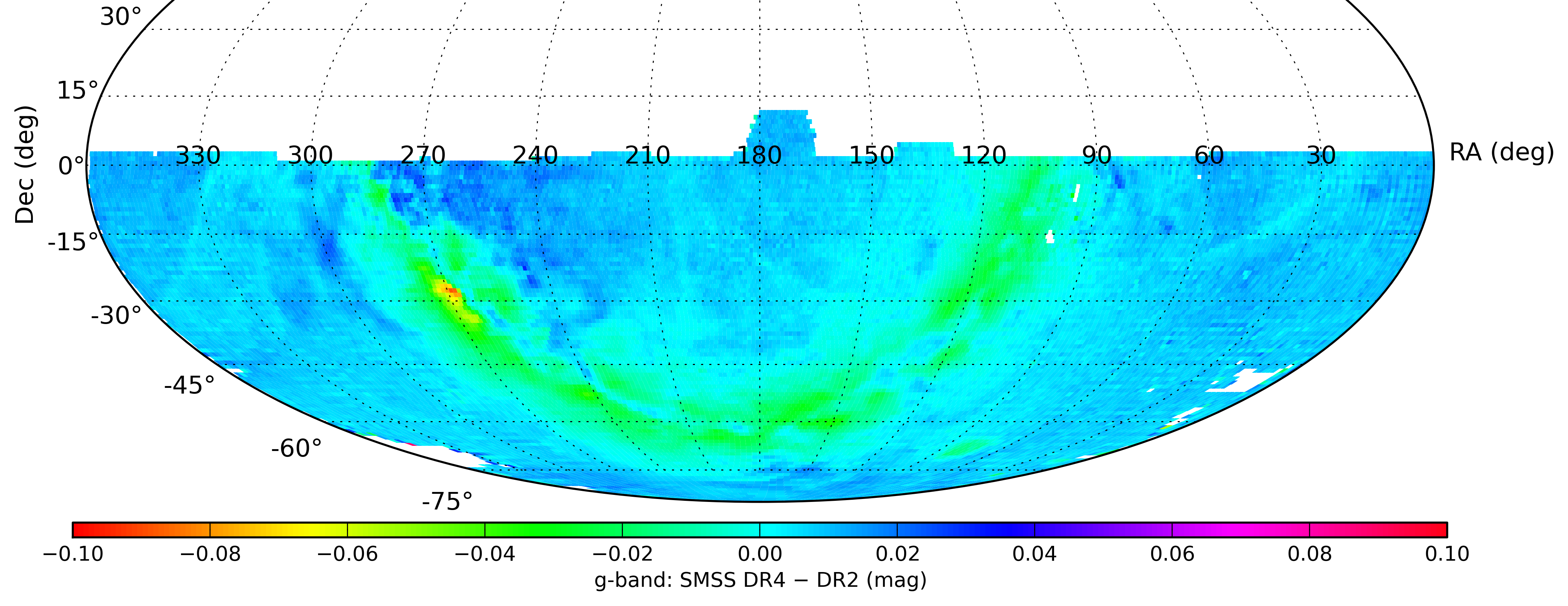
The new photometric zeropoint catalogue is anchored to Gaia low-resolution spectroscopy, which significantly improves the uniformity and precision of the calibration in u- and v-band compared to previous data releases.
The sky maps below show the median changes between DR4 and DR2 photometry.
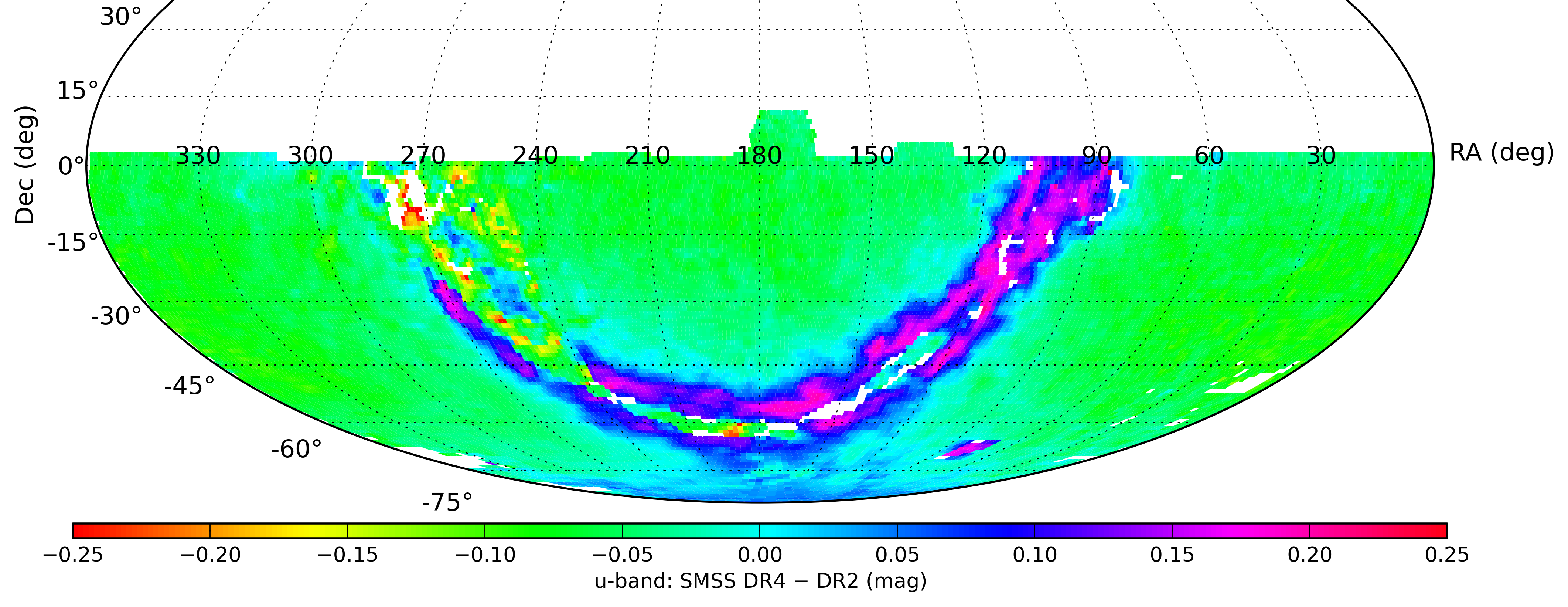

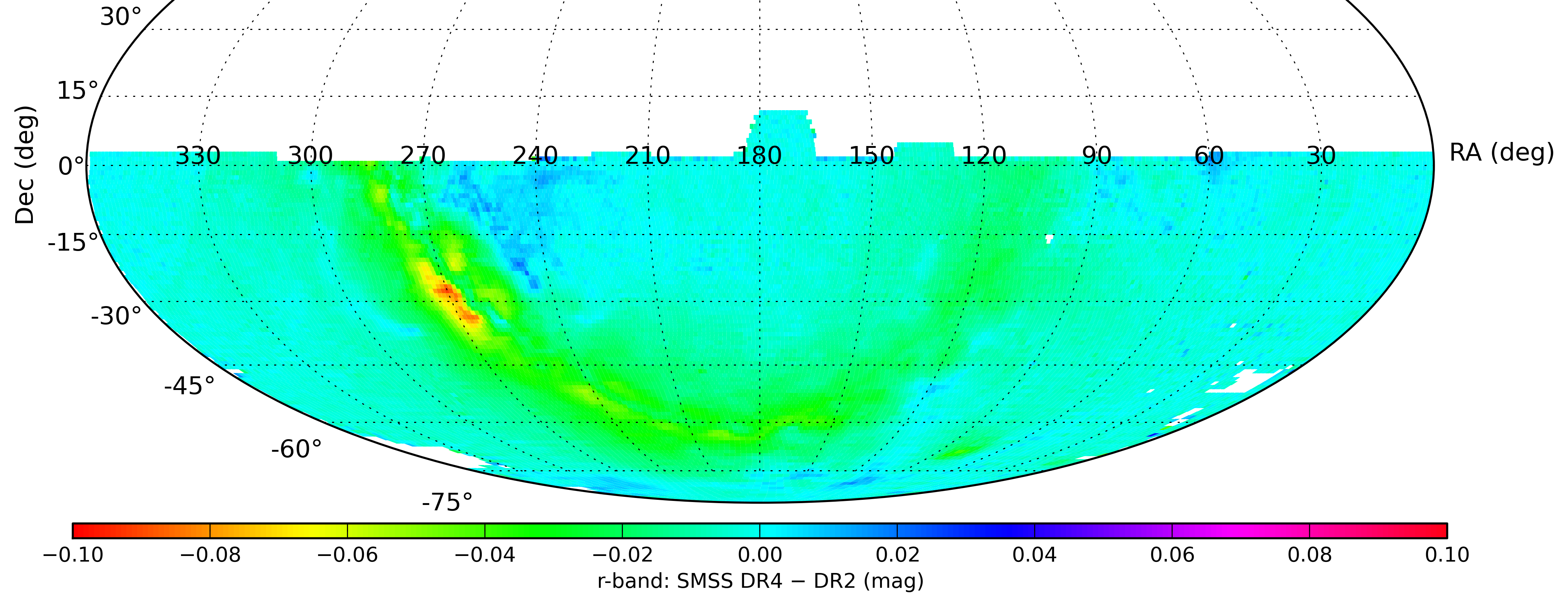
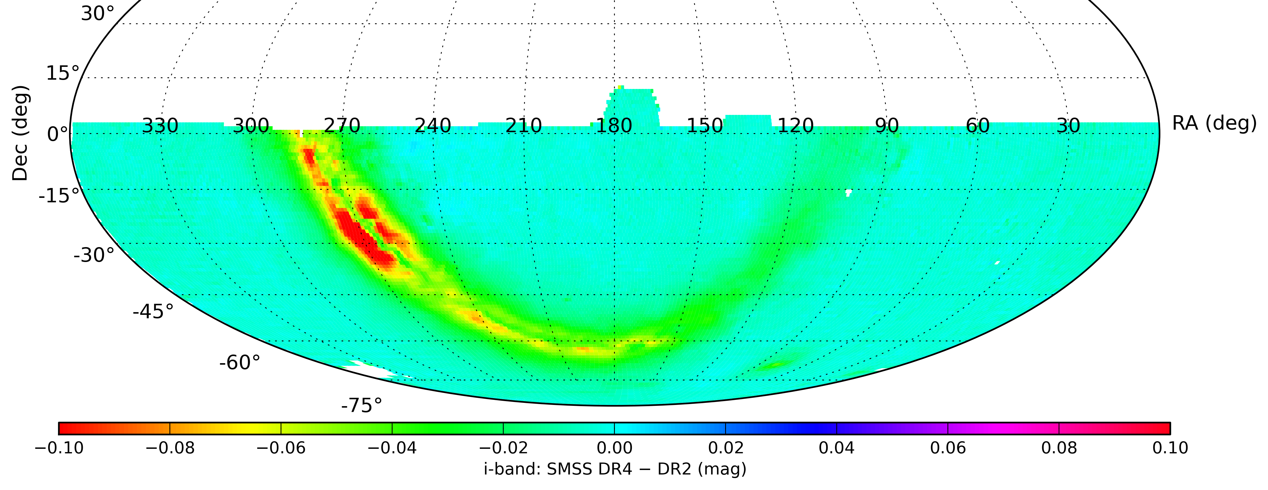
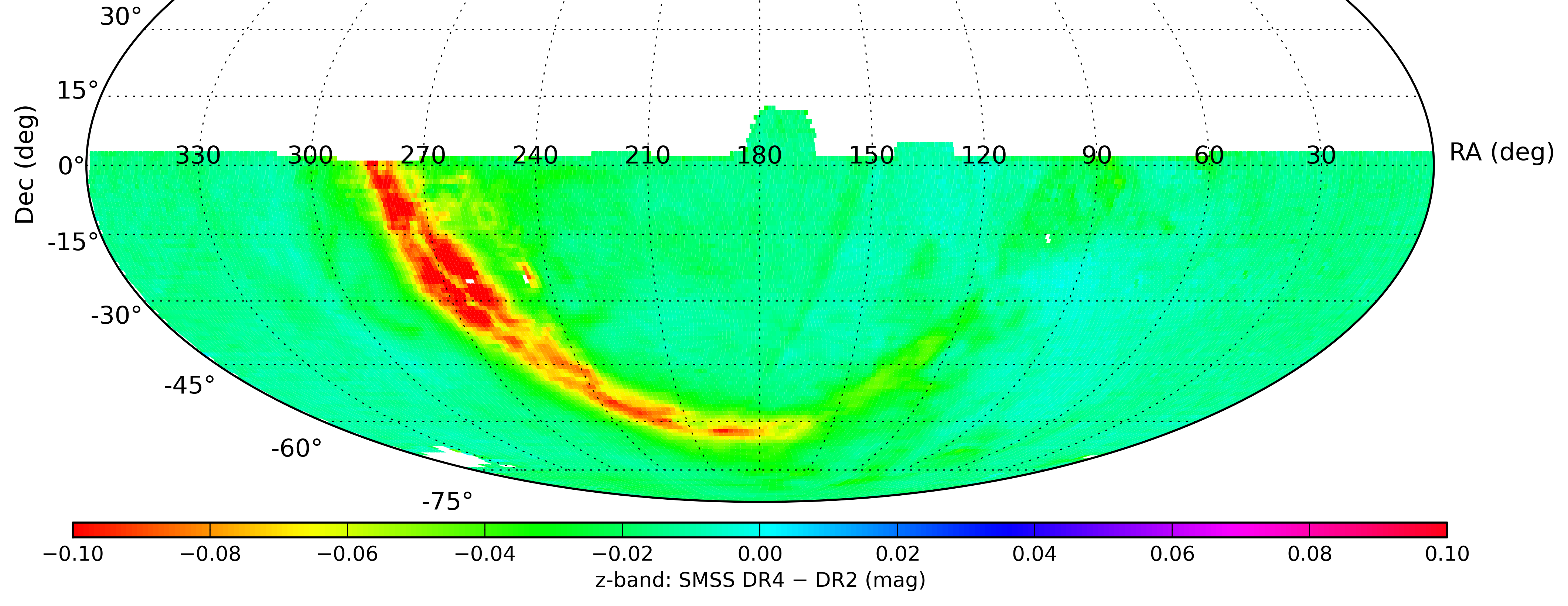
Comparison with synthetic photometry of CALSPEC standard stars shows agreement across a range of colours that is typically better than 0.02 mag. The slight residual trends in u- and v-band may be due to small (1-5 nm) shifts in the filter bandpass relative to the expected filter curves.

The internal reproducibility of SkyMapper PSF photometry of isolated bright sources is on the order of 1%.
Known Issues | DR4^ Back to top
Click on the table headings to sort the table based on that value.
| Issue ↕ | First affected release ↕ | Resolved in ↕ | Last modified ↕ |
|---|---|---|---|
| Extended-source photometry | EDR | — | Jul 13 2023, 19:26 AEST |
| Incorrect photometry when merging child objects | DR1.1 | DR4 | Jul 13 2023, 19:25 AEST |
| Spatially varying PSF affecting photometry | EDR | — | Jun 05 2017, 15:55 AEST |
| ZIP file downloads in Safari (for info) | EDR | — | May 02 2016, 12:21 AEST |